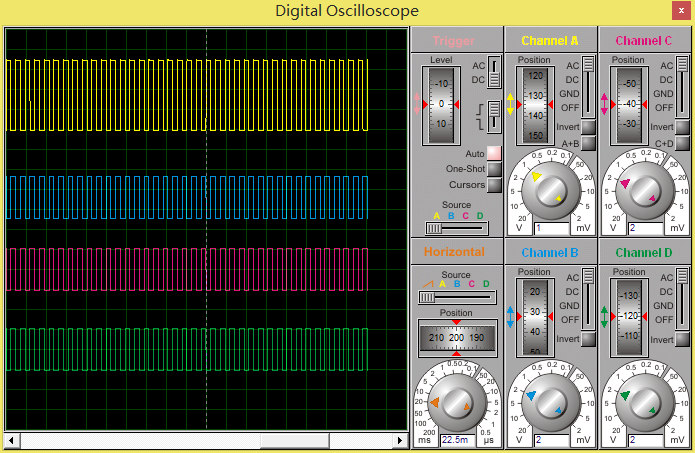
最近帮别人设计一个毕业设计,做一个多种信号发生器(四种波形:方波、三角波、锯齿波、梯形波),现在贴上来给大家参考,如果有错误的地方,望指出~
下面先贴上仿真的电路图(仿真的软件是Protuse,上传一个大点的图,方便大家看的清楚点):
原件清单:STC89C52单片机X1、DAC0832转换器X1、12M晶振X1、电容22pfX2、10uf的电容X1、1nf陶瓷电容X1、独立按键X4、10千欧排阻X1、10KΩ电阻X5、LM358 单电源运放X1。仿真就需要这些原件,具体的硬件设计大家定好了在制作~

下面上传一下C程序吧~(使用的IDE环境是Keil 4,语言是C语言)
Source文件(.c文件):
1\main.c文件:
1 #include "reg52.h"
2 #include "init.h"
3 #include "single.h"
4 #include "delay.h"
5 #include "Key.h"
6 int main(void)
7 {
8 unsigned char Model=0;//0-方波 1-三角波 2-锯齿波 3-正弦波
9 unsigned int Count=0;//计数器
10 unsigned int Squ_Per=256;
11 unsigned int Tri_Per=256;
12 unsigned int Saw_Per=256;
13 unsigned int Sin_Per=256;
14 init();
15 while(1)
16 {
17 while(Model==0)
18 {
19 Square_wave(Squ_Per,&Count);
20 Count+=4;
21 Squ_Per=Key_Plus(Squ_Per);
22 Squ_Per=Key_Subc(Squ_Per);
23 Model=Key_Model(Model,&Squ_Per,&Count);//每次退出当前while时记得复原Period和Count的数据
24 }
25 while(Model==1)
26 {
27 Triangle_wave(Tri_Per,&Count);
28 Count+=4;
29 Tri_Per=Key_Plus(Tri_Per);
30 Tri_Per=Key_Subc(Tri_Per);
31 Model=Key_Model(Model,&Tri_Per,&Count);
32 }
33 while(Model==2)
34 {
35 Sawtooth_wave(Saw_Per,&Count);
36 Count+=4;
37 Saw_Per=Key_Plus(Saw_Per);
38 Saw_Per=Key_Subc(Saw_Per);
39 Model=Key_Model(Model,&Saw_Per,&Count);
40 }
41 while(Model==3)
42 {
43 Sin_wave(Sin_Per,&Count);
44 Count+=4;
45 Sin_Per=Key_Plus(Sin_Per);
46 Sin_Per=Key_Subc(Sin_Per);
47 Model=Key_Model(Model,&Sin_Per,&Count);
48 }
49 }
50 return 0;
51 }
2\init.c文件:
1 #include "reg52.h"
2 sbit CS_DAC=P1^5;//DAC0832的片选端口
3 sbit WR_DAC=P1^6;//DAC0832的数据写入端口
4 extern void init(void)
5 {
6 P0=0xff;
7 P1=0xff;
8 P2=0xff;
9 P3=0xff;
10 CS_DAC=0;//一直片选中DAC0832,低电平有效啊~
11 WR_DAC=0;//一直写入数据到DAC0832
12 }
3\single.c文件
1 #include "reg52.h"
2 #include "single.h"
3 #include "delay.h"
4 #define DATA P0
5 void Square_wave(unsigned int Per,unsigned int *Count)
6 {
7 if(*Count>=Per) *Count=0;
8 if(*Count 9 { 10 DATA=0x00; 11 } 12 else 13 { 14 DATA=0xFF; 15 } 16 } 17 void Triangle_wave(unsigned int Per,unsigned int *Count) 18 { 19 if(*Count>=Per) *Count=0; 20 if(*Count 21 { 22 DATA=*Count; 23 } 24 else 25 { 26 DATA=Per-*Count; 27 } 28 } 29 void Sawtooth_wave(unsigned int Per,unsigned int *Count) 30 { 31 if(*Count>=Per) *Count=0; 32 if(*Count 33 { 34 DATA=*Count; 35 } 36 } 37 void Sin_wave(unsigned int Per,unsigned int *Count) 38 { 39 if(*Count>Per) *Count=0; 40 if(*Count 41 { 42 DATA=*Count; 43 } 44 else if(*Count==Per/2) 45 { 46 delay(100); 47 } 48 else if(*Count 49 { 50 DATA=Per-*Count; 51 } 52 else if(*Count==Per) 53 { 54 delay(100); 55 } 56 } 4\Key.c文件: 1 #include "Key.h" 2 #include "delay.h" 3 sbit key2=P3^3; //wave Change 4 sbit key3=P3^4; //Fre plus 5 sbit key4=P3^5; //Fre subc 6 unsigned char Key_Model(unsigned char Model,unsigned int *Pre,unsigned int *Count) 7 { 8 if(key2==0) 9 { 10 delay(10); 11 if(key2==0) 12 { 13 Model=Model+1; 14 *Pre=256; 15 *Count=0; 16 } 17 } 18 while(key2==0); 19 if(Model>3) 20 { 21 Model=0; 22 } 23 return Model; 24 } 25 unsigned int Key_Plus(unsigned int Per) 26 { 27 if(key3==0) 28 { 29 delay(10); 30 if(key3==0) 31 { 32 Per=Per+8; 33 } 34 } 35 while(key3==0); 36 if(Per>256) 37 { 38 Per=0; 39 } 40 return Per; 41 } 42 unsigned int Key_Subc(unsigned int Per) 43 { 44 if(key4==0) 45 { 46 delay(10); 47 if(key4==0) 48 { 49 Per=Per-8; 50 } 51 } 52 while(key4==0); 53 if(Per<0) 54 { 55 Per=256; 56 } 57 return Per; 58 } 5\delay.c文件: 1 void delay(unsigned int r) 2 { 3 unsigned int i,j; 4 for(i=r;i>0;i--) 5 for(j=110;j>0;j--); 6 } Header文件(.h文件): 1\init.h文件: 1 extern void init(void); 2\single.h文件: 1 void Square_wave(unsigned int Per,unsigned int *Count); 2 void Triangle_wave(unsigned int Per,unsigned int *Count); 3 void Sawtooth_wave(unsigned int Per,unsigned int *Count); 4 void Sin_wave(unsigned int Per,unsigned int *Count); 3\Key.h文件: 1 #include "reg52.h" 2 unsigned char Key_Model(unsigned char Model,unsigned int *Pre,unsigned int *Count); 3 unsigned int Key_Plus(unsigned int Per); 4 unsigned int Key_Subc(unsigned int Per); 4\delay.h文件: 1 #include 2 void delay(unsigned int r); 3 #define NOP() _nop_() 所用的工程文件我都已经上传喽~,下面来看看仿真的结果:(大家在电路设计的时候可以进行一下滤波处理,然后对信号进行放大处理,这样的话效果可能会更好点哦~) 方波: 三角波: 锯齿波: 梯形波: 大家转载请注明出处!谢谢! 在这里要感谢GISPALAB实验室的各位老师和学长学姐的帮助!谢谢~ 大家注意下,电路有个小问题,由于本人的失误,DAC0832的Iout1和Iout2的输出接口的接法应该按如下的接入方式: 需要修改的地方有: 1、电源改成双电源 2、Iout接口需要接地 感谢GISPALAB实验室的老师和同学们的帮助和支持~


 修改完毕之后的结果就会比较完美了,下面上传一个三角波的波形
上一篇:51单片机串口收发设计的思考
下一篇:单片机DA转换实现正弦波
推荐阅读最新更新时间:2024-03-16 15:30


 电子电路实用原理图300例
 STC51单片机程序与仿真练习
 控制系统计算机辅助设计 — MATLAB语言与应用


 京公网安备 11010802033920号