Abstract: The MAX1253/54 and MAX1153/54 system monitors are a low cost solution for monitoring multiple temperatures in a system. This application note explains how to measure temperature using remote sensing diodes in single-ended or differential configuration and possible error sources.
Remote temperature monitoring traditionally has been accomplished with thermistors, thermocouples or temperature sensor ICs. If a system requires temperature measurements in multiple locations, the costs can quickly add up. The MAX1253/1254 and MAX1153/1154 provide a low-cost solution to monitor multiple remote temperatures as well as a single local temperature. In addition, these devices offer autonomous alarming functions without any interaction required by a host controller, generating an interrupt when a user programmable upper or lower threshold is exceeded, resulting in fully stand-alone temperature monitoring.
These IC devices monitor both arbitrary voltages and temperature, however this article will focus specifically on temperature monitoring and is therefore intended as a supplement to the MAX1253/54 and MAX1153/54 data sheet, which covers all the capabilities of the devices. Please see the device data sheet for alarming functions, device programming, specifications, etc.
Temperature = (VHIGH - VLOW) × q/(n × k × ln(IHIGH/ILOW) (°K)
Where:
VHIGH = sensor diode voltage with high current flowing (IHIGH)
VLOW = sensor diode voltage with low current flowing (ILOW)
q = charge of electron = 1.602. 10-19 Coulombs
k = Boltzman's constant = 1.38. 10-23 J/K
n = ideality factor = 1
To make temperature measurements using this method, the device performs two measurements using two separate constant current sources. The ratio between IHIGH and ILOW is trimmed at the factory. The device then calculates the temperature using the above equation and writes the result to the output register in °C.
Refer to Maxim application note: "Compensating for Ideality Factor and Series Resistance Differences between Thermal Sense Diodes", for additional information on the ideality factor.
The MAX1253/MAX1254 and MAX1153/MAX1154 support both single?ended and differential temperature measurements or any combination of each. The design decision between the two types of measurement depends on the desired level of accuracy and on type or number of temperature sensors.

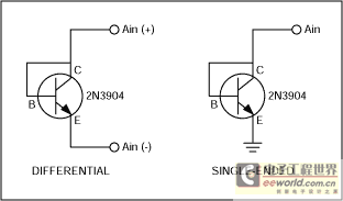
Figure 1. Connecting differential and single-ended temperature sensors.
Single-ended mode require a fewer number of connections per channel resulting in a simpler implementation with up to eight monitored temperatures for each IC device. Implementation is easy, just connect the anode of a diode-connected transistor to the input channel and the cathode to ground.
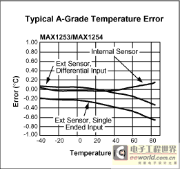
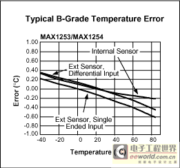
Differential-mode measurement allows for higher accuracy by providing common-mode rejection, but only allows four individual temperatures to be monitored for each IC device. Connect the anode of a diode-connected transistor to the even input channel and the cathode to the odd input channel of an input pair configured for differential temperature measurement. Figure 1 shows the diode connection. Please refer to Figures 2 and 3 for the typical temperature error for single-ended or a differential sensor.

Figure 2. Typical A-grade temperature error.

Figure 3. Typical B-grade temperature error.
For single-ended measurements, choose ground connections for sensors away from high current return paths to avoid the introduction of errors caused by voltage drops in the board/system ground, the main drawback for single ended measurements. Practical options for better accuracy performance are the use of a star configured subsystem ground, or a signal ground plane. Isolate the anode sensor connection trace away from board and system noise sources; shield it with ground lines and ground planes (when available) to prevent accuracy degradation in the temperature measurements caused by magnetic/electric noise induction.
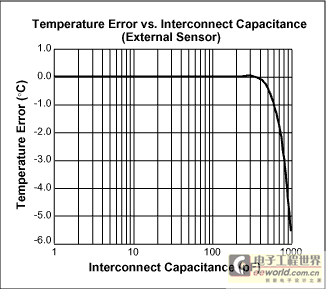
For differential measurements, run the two sensor connection lines parallel to each other with minimum spacing. This will improve temperature measurement accuracy by minimizing the differential noise between the two lines, since they will have equal exposure to most sources of noise. For further improved noise rejection, shield the two sensor connections by running them between ground planes, when available. You should minimize the capacitance between the AIN(+) and AIN(-) terminals as much as possible. Figure 4 shows the effect of this capacitance on the analog inputs when making a differential temperature measurement. One connection option is to use RG-6 cable, which has a capacitance of 50-75pF/M. This means that the device can tolerate up to 4 meters of this type of cable without significant impact to performance.

Figure 4. Effect of external sensor capacitance.
To help further reduce noise, the MAX1253/54 and MAX1153/54 have an on-chip averaging function that can be enabled. It can be programmed to average the result from 1 (no averaging) to 2048 times. The effect of averaging reduces the noise approximately by a factor of 1/sqrt(N).
Table 1. Remote Sensor Transistor Manufacturers
编辑:神话 引用地址:温度监测使用MAX1253/54和MAX1153/54-Te
Remote temperature monitoring traditionally has been accomplished with thermistors, thermocouples or temperature sensor ICs. If a system requires temperature measurements in multiple locations, the costs can quickly add up. The MAX1253/1254 and MAX1153/1154 provide a low-cost solution to monitor multiple remote temperatures as well as a single local temperature. In addition, these devices offer autonomous alarming functions without any interaction required by a host controller, generating an interrupt when a user programmable upper or lower threshold is exceeded, resulting in fully stand-alone temperature monitoring.
These IC devices monitor both arbitrary voltages and temperature, however this article will focus specifically on temperature monitoring and is therefore intended as a supplement to the MAX1253/54 and MAX1153/54 data sheet, which covers all the capabilities of the devices. Please see the device data sheet for alarming functions, device programming, specifications, etc.
Basic Diode Temperature Measurements
The forward voltage of a diode or diode-connected transistor (VBE) when operating at a constant current exhibits a negative temperature co-efficient of approximately 2mV/°C which can be used to measure the temperature at a remote diode. However, VBE can vary between diode manufacturers or even from device-to-device making absolute temperature measurements unpractical for volume production since calibration is required for each sensor. An alternate technique, which compensates for VBE variation uses measurements from two known currents to calculate temperature. This measurement depends on the ratio, rather than the absolute, and is inherently more accurate. The following equation is used in the MAX1253/1254 and MAX1153/1154.Temperature = (VHIGH - VLOW) × q/(n × k × ln(IHIGH/ILOW) (°K)
Where:
VHIGH = sensor diode voltage with high current flowing (IHIGH)
VLOW = sensor diode voltage with low current flowing (ILOW)
q = charge of electron = 1.602. 10-19 Coulombs
k = Boltzman's constant = 1.38. 10-23 J/K
n = ideality factor = 1
To make temperature measurements using this method, the device performs two measurements using two separate constant current sources. The ratio between IHIGH and ILOW is trimmed at the factory. The device then calculates the temperature using the above equation and writes the result to the output register in °C.
Refer to Maxim application note: "Compensating for Ideality Factor and Series Resistance Differences between Thermal Sense Diodes", for additional information on the ideality factor.
Using the MAX1253/1254 and MAX1153/54
The temperature measurement process in the MAX1253/MAX1254 and MAX1153/54 is fully automated. Switching of the current sources and VBE measurements are internally sequenced and require no user intervention. The resulting 12-bit (MAX1253/1254) and 10-bit (MAX1153/1153), 2's complement result represents the sensor temperature in degrees Celsius, with 1LSB = 0.125°C (12-bit) and 1LSB = 0.5°C (10-bit).The MAX1253/MAX1254 and MAX1153/MAX1154 support both single?ended and differential temperature measurements or any combination of each. The design decision between the two types of measurement depends on the desired level of accuracy and on type or number of temperature sensors.

Figure 1. Connecting differential and single-ended temperature sensors.
Single-ended mode require a fewer number of connections per channel resulting in a simpler implementation with up to eight monitored temperatures for each IC device. Implementation is easy, just connect the anode of a diode-connected transistor to the input channel and the cathode to ground.
Differential-mode measurement allows for higher accuracy by providing common-mode rejection, but only allows four individual temperatures to be monitored for each IC device. Connect the anode of a diode-connected transistor to the even input channel and the cathode to the odd input channel of an input pair configured for differential temperature measurement. Figure 1 shows the diode connection. Please refer to Figures 2 and 3 for the typical temperature error for single-ended or a differential sensor.

Figure 2. Typical A-grade temperature error.

Figure 3. Typical B-grade temperature error.
Sources of Error
Due to the small signals associated with temperature measurements, proper layout techniques are important to minimize noise coupled into the analog inputs.For single-ended measurements, choose ground connections for sensors away from high current return paths to avoid the introduction of errors caused by voltage drops in the board/system ground, the main drawback for single ended measurements. Practical options for better accuracy performance are the use of a star configured subsystem ground, or a signal ground plane. Isolate the anode sensor connection trace away from board and system noise sources; shield it with ground lines and ground planes (when available) to prevent accuracy degradation in the temperature measurements caused by magnetic/electric noise induction.
For differential measurements, run the two sensor connection lines parallel to each other with minimum spacing. This will improve temperature measurement accuracy by minimizing the differential noise between the two lines, since they will have equal exposure to most sources of noise. For further improved noise rejection, shield the two sensor connections by running them between ground planes, when available. You should minimize the capacitance between the AIN(+) and AIN(-) terminals as much as possible. Figure 4 shows the effect of this capacitance on the analog inputs when making a differential temperature measurement. One connection option is to use RG-6 cable, which has a capacitance of 50-75pF/M. This means that the device can tolerate up to 4 meters of this type of cable without significant impact to performance.

Figure 4. Effect of external sensor capacitance.
To help further reduce noise, the MAX1253/54 and MAX1153/54 have an on-chip averaging function that can be enabled. It can be programmed to average the result from 1 (no averaging) to 2048 times. The effect of averaging reduces the noise approximately by a factor of 1/sqrt(N).
Selecting a Remote Temperature Sensor
Temperature sensing accuracy depends on having a good-quality, diode-connected small-signal transistor as a sensor. Accuracy has been experimentally verified for 2N3904-type devices. The transistor must be a small-signal type with low base resistance. Tight specifications for forward current gain (+50 to +150, for example) indicate that the manufacturer has good process controls and that the devices have consistent VBE characteristics. CPU on-board sensors and other ICs' on-board temperature-sensing devices can also be used.Table 1. Remote Sensor Transistor Manufacturers
|
|
|
| Central Semiconductor (USA) |
|
| Fairchild Semiconductor (USA) |
|
| Motorola (USA) |
|
| Rohm Semiconductor (Japan) |
|
| Siemans (Germany) |
|
| Zetex (England) |
|
上一篇:介绍DS1847用于工业控制-Introduction of
下一篇:电路实现基于PC的电压测量-Circuit Enables
小广播
热门活动
换一批
更多
最新电源管理文章
更多精选电路图
更多热门文章
更多每日新闻
- Allegro MicroSystems 在 2024 年德国慕尼黑电子展上推出先进的磁性和电感式位置感测解决方案
- 左手车钥匙,右手活体检测雷达,UWB上车势在必行!
- 狂飙十年,国产CIS挤上牌桌
- 神盾短刀电池+雷神EM-i超级电混,吉利新能源甩出了两张“王炸”
- 浅谈功能安全之故障(fault),错误(error),失效(failure)
- 智能汽车2.0周期,这几大核心产业链迎来重大机会!
- 美日研发新型电池,宁德时代面临挑战?中国新能源电池产业如何应对?
- Rambus推出业界首款HBM 4控制器IP:背后有哪些技术细节?
- 村田推出高精度汽车用6轴惯性传感器
- 福特获得预充电报警专利 有助于节约成本和应对紧急情况
更多往期活动
- 【抢楼】正式开始!来抢TI LM3S811评估板吧!!!
- 有奖活动|登陆泰克高精度电源测试知识星球,揭开噪声的迷雾,发现真实的信号!
- 初识易电源——聊聊你眼中的易电源!
- 独家拆解 | 语音控制在真无线立体声TWS耳机上的创新应用
- TI EP类课程年度精选出炉,推荐分享赢好礼!
- EE邀你一起来玩NXP RAPID IOT套件
- TI 最新CapTIvate™ 触控微控制器技术直播开始报名喽!报名参与有礼呦!
- 【EEWORLD第三十九届】2012年06月社区明星人物揭晓!
- Silicon Labs BG22-EK4108A 开发套件 用科技连接未来 申请进行时!
- 泰克 4200A-SCS 带您走进半导体材料测试世界 下载赢好礼!
11月16日历史上的今天
厂商技术中心

 5962F9675601VPA


 京公网安备 11010802033920号